|
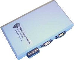
The USB- Dataspy can you over
the USB- port connect to a Windows 98, ME, 2000 or XP- PC.
As feature, you can not only spy a RS232- connection, you can spy a RS422
/ RS485 as 2 and 4- lines or RS485 and LIN-Bus, too. On RS232 are the
data and directions correctly protocoling. (the Mini I and II cannot it
so good). A speed from 230 KBaud are never a problem. With special functions
can BinTerm measure baud rates and frequency.
All inputs are saved for hyper voltage - so, your PC is saved.
The query from the serial ports are independent from Windows- drivers,
the included firmware is self write. The system is open for extensions
with new functions every time. The USB- Dataspy can you use for self-
developing with first steps to learning or save your development time
and make only a extension- board.
On the extension- connector, you can connect boards for other connections.
Just is a CAN- board available.
|
|
Display with the LED:
After press from  - button, the red LED shining for a short time. Every time, when BinTerm
install the USB- Dataspy, do the red LED shining for a short time. When
the LED is blinking, the USB- Dataspy has recognize a defect of the hardware.
- button, the red LED shining for a short time. Every time, when BinTerm
install the USB- Dataspy, do the red LED shining for a short time. When
the LED is blinking, the USB- Dataspy has recognize a defect of the hardware.
When the USB- Dataspy send data over RS232 RS422/485 or LIN, then the
LED shine so long green as the data are sending.
On parity- or frame- error shine the LED for 0,4 seconds with a red color..
When the USB- Dataspy send data over CAN- bus, the green LED goes for
a short time on.
The errors of the bus let the error- counter from chip SJA1000 from Philips
counting up. When these counter is set, the red LED is shining. Every
good received telegram decrement the error counter, if it is zero, the
red LED goes off. BinTerm protocoling up to 60 CAN- bus- errors!
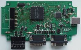
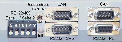
pin assignment from serial port - connection schematic:
Normally, the serial data are from SPS- side and PC- side going through
the micro controller. With these method can BinTerm insert a data- telegram
into the data- stream.
From USB- dataspy- main- board from 26.02.2003 (see the date on the board)
you can with jumper K8 and K9 through the USB- board lead the data stream,
without the data stream goes through the micro controller. But in these
working mode, you can't insert a telegram in the datastream with BinTerm,
also sending- feature can't send. The advantage: When the USB- dataspy
is out of power (no USB- cable connected) is the serial data stream not
interrupted, so the system is ideal for long time protocol with a laptop.
Occupancy of the CAN interface:
Both CAN interfaces are connected in the circuit board 1:1. You can separate
an existing CAN connection and plug in at the USB-Dataspy. The plug occupancy
is shown under "4.2 Connector from CAN- ports".
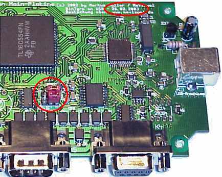 |
On
the right top is the date printed.
On top from the RS232- connector SPS- side are the jumper K8 and K9.
When both jumper are connected right, the serial data go through the
micro controller, when both jumper are left, so the serial signals
RxD and TxD are 1:1 connected.
To alter these mode, you must open the case from USB- dataspy. |
|


 Prior
Prior